Create comprehensive manufacturing documentation
E3.formboard is a complete solution for creating cable harness drawings for manufacturing. On any sheet size, one or more manufacturing drawings can be created. Automatic functionality makes the placement, arrangement and dimensioning of the harness and its segments easier. E3.formboard is fully integrated with E3.cable. The logical interconnection data defined in E3.cable is used directly in E3.formboard, and any changes made in either module are automatically reflected.
Create comprehensive manufacturing documentation
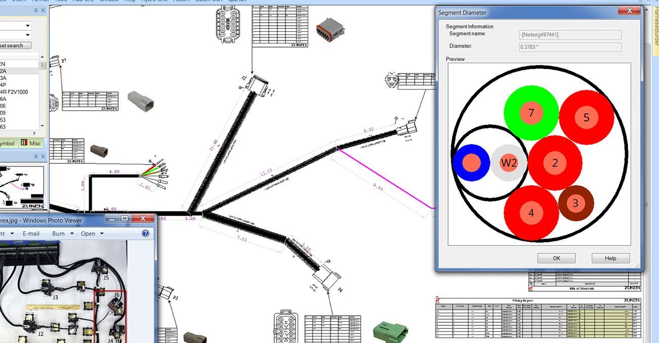
Automatic calculation of wire lengths and bundle diameters
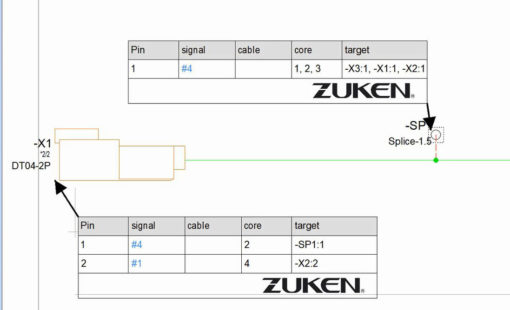
Dynamic connector tables with pin, wire, cable, signal, gauge, color, and target information
Control and adjustment of wire lengths
Start Your Test Drive Today
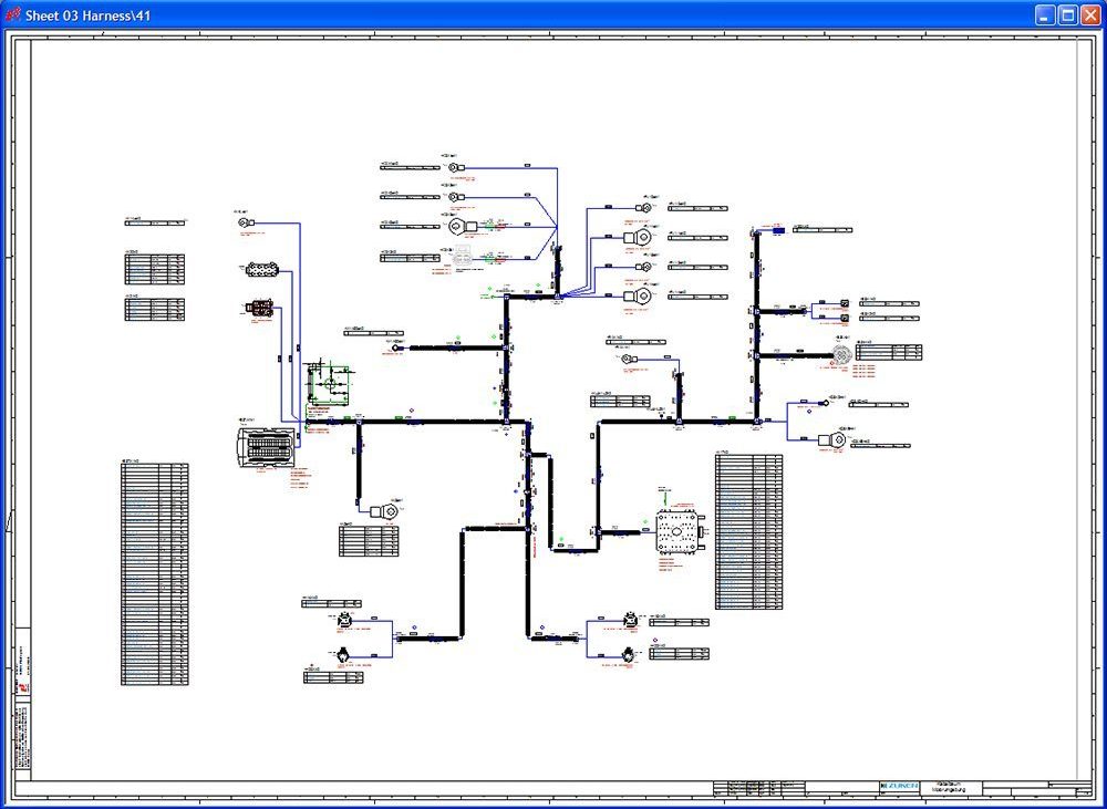
Formboard designs include connection tables, clips, heat-shrink and convolute. Wire lengths are automatically determined and a packing algorithm calculates the outside diameter of the harness segments. To fit to paper size, harness branches are rotated about any point and special print functionality allows individual sections to be reprinted.
Connectors added to the harness sheet automatically include connection tables, while connect lines added between the connectors define the branches of the harness. Wires added to the pins in the connection tables are automatically routed through the shortest or pre-defined harness segments.
With E³.formboard’s integration with E³.cable, the logical interconnection data defined in E³.cable is used directly in E³.formboard. Any changes made in either module are automatically reflected in the other.
E3.formboard provides a complete solution for creating cable harness drawings for manufacturing.
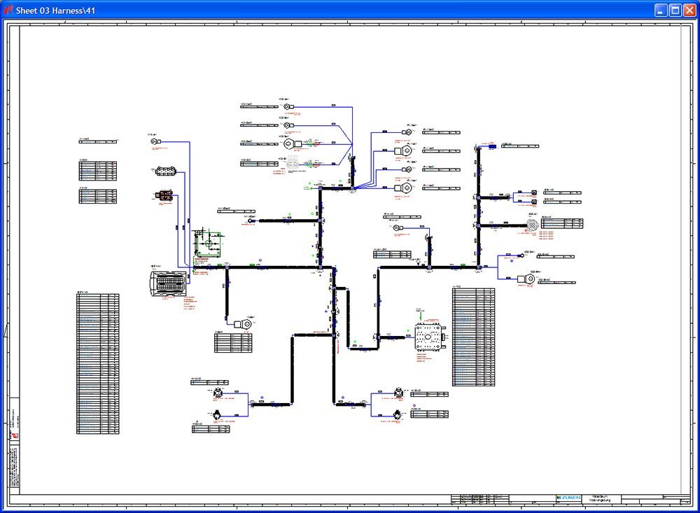
E3.formboard drawings provide a view of the cables and harnesses as defined in the schematic diagram.They comprise both electrical and non-electrical components including connector placement, wire segments, protective coverings, clips, labels etc.
Wire lengths are automatically determined and a packing algorithm calculates the outside diameter of the harness segments. To fit to paper size, harness branches can be rotated about any point and special print functionality allows individual sections to be reprinted
Configurable connector tables can be placed in the drawing to display pin, wire, cable, signal, gauge, color, and target information. These tables are dynamic, meaning that a wire can be added to a pin displayed in the table and connected to a pin in another table and Formboard will automatically route the wire from pin to pin through the harness segments.
Harness segments can be highlighted when the length displayed on the sheet does not correspond to the manufacturing length defined for each segment. These ‘out-of-scale’ segments can be automatically adjusted to display the correct manufacturing length assigned to the segments of the harness.
E3.formboard is fully integrated with E3.cable. The logical interconnection data defined in E3.cable is used directly in E3.formboard and any changes made in either module are automatically reflected in the other.
Manufacturing data can be extracted from the design in the form of wire lists, which include route and length information. Modules interface E3.panel to manufacturing equipment such as Komax wire preparation machinery and Perforex drilling, punching and cutting tools.
ECAD offers many advantages over traditional manual processes with the ability to select parts from a vast database of smart components and synchronization with your business systems like ERP to drive a complete quotation based on the design.
Find out more via our webinars, blogs, press releases and more...